Current situation
Waddrisco Baolongmen Machining Center is the gantry machining center imported by our company in 1992. The CNC system is Siemens SINUMERIK 850ME and the PLC is Siemens SIMATICS S5-150. The spindle and each feed axis are equipped with DC motor for Siemens DC speed control system. The machine tool is responsible for the precision machining of the locomotive diesel engine body. Workbench 2 000mm × 5 000mm, double workbench. The mechanical complexity factor is 110 and the electrical complexity factor is 180. After a long period of use, the electrical system of the equipment has been seriously aging, the failure rate has increased, and the equipment maintenance time is too long, especially the spindle electrical faults frequently occur.
The original spindle drive of this machine is S IEMENS6RA27-6DV34, and the spindle drive motor is MW 5284/1Q. Since the DC motor uses a commutator for commutation, it is determined from the mechanical structure that it must frequently inspect and maintain the commutating part during use. If necessary, the motor must be disassembled to machine the commutator surface. It takes time and effort and the failure rate is relatively high. In addition, the use of the machine tool is long, the DC drive thyristor is often burned, the printed circuit board is seriously deteriorated, the spare parts that need to be replaced during maintenance have been discontinued, and it is more and more difficult to purchase new spare parts.
Spare parts costs are getting higher and higher. Maintenance is very difficult. In the event of a malfunction of the machine tool, it will seriously affect the production of the diesel engine. According to the status quo of the equipment, our company decided to carry out electrical transformation of its main shaft part.
2. Technical research
The DC servo system is a system that controls the DC motor. The DC motor is flexible, convenient and easy to adjust. It is the main actuator of the CNC machine tool spindle and feed axis, but its commutator and brush components are the most prone to problems, especially the commutator. It is a device made of a variety of materials, so the process is very complicated.
Furthermore, due to the inconsistent thermal expansion coefficients of various materials, the pre-stress and deformation are inconsistent, the maintenance is very difficult, and the ground carbon is soared everywhere. This conductive powder is often the cause of failure.
With the development of computer science and technology, especially the development and advancement of control theory of power semiconductors, the control technology of AC servo system has gradually matured. The AC speed regulation method of AC vector transformation proposed by Siemens has opened up a new way to make the application of AC synchronous permanent magnet motor greatly developed. From the maintenance point of view, the AC servo system is much less than the DC servo system maintenance work, especially after the permanent magnet AC servo motor is used, the maintenance workload is greatly reduced. Looking at it now, the replacement of DC servo by AC servo has become an inevitable trend of technological progress. The performance of the AC spindle drive has reached the level of the DC drive spindle and is no more expensive than DC drive.
The AC speed regulation method proposed by Siemens Company has opened up a new way, especially the rare earth material used in the manufacture of permanent magnet motor, which has greatly developed the application of AC synchronous permanent magnet motor. This transformation method focuses on the torque control of the motor, that is, controlling the horizontal axis current to control the torque, further controlling the rotational speed, and making the servo system a big step forward.
Siemens has many years of experience in supplying AC servo system and AC servo motor products. The function and precision of the products can guarantee the use of machine tools, and the after-sales service is also convenient. Moreover, the CNC system and PLC of the original machine tool are all Siemens, and many of them are in the process of transformation. The processing of interface signals is easier.
In summary, we decided to transform the spindle into a Siemens AC speed control system to replace the original DC servo motor as an AC servo motor.
3. Retrofit design
(1) Replace the original analog drive and motor with Siemens SIMODRIVE 611U digital AC drive module and 1PH7 AC spindle servo motor (1PH7186-2NE15-CA0, 60kW, N rated=1 250, Nmax=5 000, M rated=458M) (75kW, N rated=1 013/1 068, N max=3 400) to completely solve the commutation weakness of the DC motor.
(2) Re-adjust and set various CNC machine data related to the transformation, including NC data/PLC data/setting data, and maintain all the functions and features of the machine before the transformation, especially the spindle functions and features (including the gear change) range). The original SINUMERIK 850ME CNC system of the machine tool is retained for continued use.
(3) Reset the SIMODRIVE 611U PLC I/O terminal function and external redirection to keep the I/O point address associated with the spindle unchanged. If necessary, partially modify the original PLC program to ensure normal communication between the new spindle drive unit and the original PLC. The original SIMATICS S5-150 series PLC of the machine tool is retained for continued use.
(4) Re-lay the new spindle motor related power cable and signal cable.
4. Installation and commissioning
On-site installation work is divided into mechanical and electrical parts.
(1) Mechanical part: The installation work is to disassemble the original DC motor, map the new motor shaft, and make the coupling of the motor shaft and the main shaft gear box. Install a new AC motor.
(2) Electrical part: The installation work is relatively large, and the contents include: 1 Removing the original DC drive and the corresponding control device. 2 Surveying and installation of new AC drives, drive power supplies and corresponding electrical components. 3 Re-lay the new spindle motor power cable and signal cable. 4 Connection of wires and cables in the electrical cabinet. 5 Check the correctness of the installation wiring. 6 power-on debugging. Debug the performance of the AC spindle with Siemens' professional commissioning software SimoComU.
5. Technical difficulties
(1) Installation of the AC servo spindle motor. Ordering an AC servo motor installation space of the same power of 75 kW interferes and cannot be installed. The AC servo motor that meets the installation requirements has a maximum power of 60 kW.
After careful analysis and demonstration: 1 The machine tool is a finishing machine tool, and there is no arrangement in the process history that has used more than 60kW power for strong cutting. 2 It is expected that the possibility of using 60kW power in the future is small. An AC servo motor with a power of 60 kW can meet the process requirements. After the demonstration of the process department, the technical plan is feasible to agree to the transformation.
(2) Debugging the new AC drive. Connect the power line and signal line according to the pattern and power on the drive. The debugging of the drive must first be debugged with dynamic features before the position can be debugged. The dynamic debugging of the speed loop is via the SimoComU software.
The steps are as follows: 1. Connect the computer to the debug interface of the 611U AC drive with the prepared “driver debug cable†as shown in the figure. After the drive is powered up, A1106 is displayed. The display indicates that the motor has no data. The motor parameter needs to be set by the tool software SimoComU. 2 Drive enable (48, 63 and 64 are connected to T9). The speed reference of the drive is optimized by the PC in digital form. 3 Enter SimoComU; select online mode; select PC control and select “okâ€. 4 Name the drive that will be debugged and select Next. 5 Select the model of the input motor and choose Next. 6 Select the type of encoder according to the motor model and select Next. 7 Select Speed/Torque Control and choose Next. 8SimoComU lists the selected data and selects the receive driver configuration after confirming it. 9 Select to run the automatic speed controller optimization "Execute Automatic Speed ​​Controller Setting"; select 1 to 4 steps to automatically perform the optimization process. 10 Optimization ends, exit the PC control mode.

AC servo drive and PLC debug interface cable diagram
(3) Processing of input and output signals of the spindle AC drive.
According to the access method of the DC driver before the transformation, the new AC driver input and output signals are connected to the PLC, as shown in Table 1.

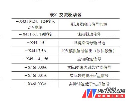
Signal 64 is pulse enabled, 63 is drive enabled, and both Tx is turned "on" and "off" by relays K31-BX, K0BX. 48 and 112, T9 termination. As shown in table 2.
(4) The original relay is changed to the problem of electronic transistor output.
At the beginning of the transformation, the design driver output -X461 000A, -X461001A and -X461 003A signals were directly input into the PLC without passing through the intermediate relay. The spindle rotation action cannot be realized during the process of machine tool modification and debugging, and the signal high and low levels are also correct. Before the machine tool was rebuilt, we carefully analyzed and recorded the signals of a large number of normal states of the machine. By comparing the recorded signals, it is confirmed that the driver output signal is correct.
After careful reading and in-depth research, we believe that it is a timing problem of the signal. The machine tool is imported from Germany, its circuit protection is complete, the safety factor is high, and the corresponding structure is complicated and difficult to repair. The machine circuit design is to first turn on the NC and PLC power, NC and PLC to work normally, and then turn on the main circuit servo and hydraulic parts. That is to say, the PLC detects the driving signal during the starting process of the main circuit of the machine. It is considered that the driving is normal and the spindle can be rotated. If the signal is not normal, the spindle cannot be rotated. The output signal circuit of the old DC servo drive is a relay structure, and the output signal does not change during the power-on of the main circuit to start the servo drive.
The process of powering up the new AC servo drive is determined by the structure of the output signal circuit; the electronic transistor circuit has no output before power-on, that is, non-zero non-one; after power-on, according to the internal software setting of the servo driver and the current state output signal of the drive . That is to say, the output signal of the new AC servo drive changes before and after power-on, and the PLC believes that the change is an abnormal state and does not allow the spindle to operate.
The key to finding the problem is the first step. In order to confirm the correct analysis, the output signal of the driver is simulated with a small switch, and the output signal does not change during the power-on process, and the spindle of the machine tool operates normally. The results of the analysis were confirmed.
Change the design to connect the output signal to the intermediate relay. After the change, there is no output signal during the power-on process, the intermediate relay coil has no voltage, and the contact does not operate. It can ensure that the previous output signal on the drive remains correct and the spindle rotation of the machine tool is normal. It has been proved that the idea is correct. The machine tool spindle is operating normally.
6. Acceptance review
After the completion of the machine tool transformation and commissioning, after two weeks of trial production, the machine tool performance fully meets the production needs, and the spindle speed, speed and positioning have reached the machine tool function. After review by the company's electromechanical equipment expert group, it is considered that the CNC gantry machining center spindle transformation project is successful, meet the transformation design requirements and meet the production needs. Since the machine tool was changed in 2009, the partial failure rate of the machine tool spindle has been zero. The cost of renovation is 280,000 yuan.
7. Conclusion
The transformation project solved the technical upgrade and transformation work of the old CNC machining center, which made the old CNC machining center rejuvenate, extended the service period of the imported CNC gantry machining center, reduced the equipment maintenance cost and reduced the equipment maintenance time. Make the equipment better serve the production.
We diviided the led light according to the using eviiroment. Most of our product is the commercial LED Lighting
Commercial lighting is a term used to describe lighting that is used in commercial spaces, including auto dealerships, distribution centers, churches, factories, offices, and warehouses. Unlike residential lighting, commercial lighting is made to withstand more abuse and has a longer lifespan.
While the focus of residential lighting is often on aesthetics, commercial lighting is task orientated. Commercial lighting systems are designed based on what the application is. For example, in an office-type setting, you may see task lighting, which illuminates specific areas where employees need concentrated light to be able to perform their jobs.
Cylinder Ceiling Light,Ceiling Lights For Living Room,Black Ceiling Light,Led Ceiling Lights Dimmable
Jiangmen Dilin Lighting High-Tech Co., Ltd. , https://www.jmdilinlighting.com