Cimatron's most widely used three-axis milling programming for cavity mold machining, using its original intelligent NC programming technology based on blank margin knowledge, combined with the unique features of machining mold parts, makes it the most desirable type today. One of the cavity mode CAM solutions. The following is a combination of Cimatron's application in actual machining to introduce its common strategy for CNC machining of cavity molds.
1 Common strategies for Cimatron cavity mold NC machining
In the three-axis CNC milling of cavity mold parts, the milling process from general shape blank to finishing (mainly polishing) can be divided into roughing, semi-finishing, finishing and clearing. Processing four types of processes.
In roughing of blanks, although other forms of machining such as inserting can be used, contour cutting is still the most common form of actual machining. Cimatron offers three processes, POCKET, ZCU T, and WCU T, to support this form of processing. The WCU T-ROU GH process is the most commonly used roughing process due to its high efficiency of circumferential cutting and intelligent feed setting and unique interlayer processing.
The ideal semi-finishing should be based on the residuals of the roughed blank for tool path calculation. Cimatron has a unique best pre-optimization technique, using the WCU T-ROU GH process and selecting the WITHSTOCK option in the machining parameters to make the tool The trajectory is generated according to the residual condition of the blank after roughing, which not only completely eliminates the empty knife phenomenon, but also makes the cutting load of the tool more reasonable and the trajectory is smoother, which can generate a more ideal semi-finished tool path than the post-optimization technique. By reasonably setting the inter-layer processing parameters, the residual of the blank between the two cutting layers can be removed by reworking along the processing surface, which can be achieved by reducing the height of the layer to improve the surface processing accuracy of the part. Under the premise of the same effect, the processing efficiency is greatly improved.
For part finishing, Cimatron offers a wide range of machining processes to support different finishing methods. Such as SURMILL (parameter line processing), SURCLR (limited line processing), SRFPKT (edge ​​processing), 3D STEP (three-dimensional step processing) and WCU T - FIN2ISH (contour processing), among which SRFPKT for the entire part surface And WCU T - FINISH is the most commonly used.
For the entire processing surface, it is always unreasonable to use a finishing process. For the flat surface whose slope is close to the horizontal plane, the SRFPKT process is better for the surface machining, while the steep surface with the slope close to the vertical surface is generally better for the WCU T-FINISH process. Therefore, it is first necessary to carry out slope analysis on the machined surface, and then adopting the appropriate form of the cutter according to the different characteristics of the machined surface is the most ideal processing method. Using the WCU T-FINISH process, and selecting BETWEEN LAYERS : HORIZ in the machining parameters, the slope of the machined surface can be automatically analyzed, and different processing forms can be used for different areas according to the analysis results.
The local root-cleaning process is also essential for the processing of the mold. In addition to the REMACHINE: PENCIL based on the rounded center on the model for single-pass rooting, REMACHINE:CL EANUP can be used for multi-channel reciprocating automatic cleaning based on the blank margin. Root, in order to achieve smooth cutting and uniform load. With this process, the steep slope and flat regions can be automatically processed separately using the region slope analysis algorithm, and the corresponding tool paths are generated.
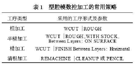
The common strategies for CNC machining of cavity molds are shown in Table 1.
2 Processing parameters setting of Cimatron typical cavity mold parts
Typical cavity mold parts have cores, cavities, and electrodes for EDM. In each process, especially in the roughing process, different processing parameters should be set according to the different characteristics of the parts to achieve the desired processing results. The following is a description of the typical parameter settings for roughing various types of parts.
2.1 Processing of cavity parts
For roughing of general cavity parts, the WCU T — ROU GH procedure can be used. According to the characteristics of such parts, the following settings can be made in the processing parameter table:
(1) The path mode parameter is generally set to SPIRAL CU T to make the tool around the machining plane for circumferential cutting.
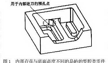
(2) The type parameter of the machining model is generally set to OPENPART: NO to limit the machining within the machining range. If there are islands inside the part that are different in height from the bottom of the cavity, as shown in Figure 1, it should be set to OPEN + ISLAND to feed the blanks or internal pre-holes on different cutting layers.
(3) The feed parameter is generally AU TO ENTRYPOINTS. When it is necessary to drill the pre-hole point, it can be set to OPTIMIZED ENTRY PNT (with optimized feed point), and set CREATE ENTRY PNT : YES to produce There are fewer pre-hole points, as shown in Figure 1.
(4) The feed angle parameter RAMP AN GL E is generally set to 5° to 10° to use the helical feed and the cutting order parameter is set to INSIDE OU T to facilitate the generation of the helix. The spiral radius can be adjusted by resetting the MAX RAMP RADIUS parameters if necessary.
(5) For deeper cavity machining, such as the use of tools with machining dead zones (such as ring cutters with carbide inserts), a knife may appear when cutting down. By setting MIN PLUN GESIZE to the tool diameter minus twice the fillet radius, you can prevent cuts into areas where the machining range is too small to avoid possible hazards.
2.2 Processing of core parts
For roughing, the WCU T-ROU GH process is also used.
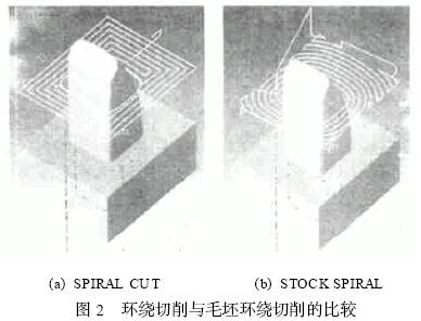
(1) The path mode parameter can be set to STOCK SPIRAL to make the tool around the blank for cutting to improve the cutting efficiency of the blank. Figure 2 shows the different roughing tool paths generated for the same part using the SPIRAL CU T and STOCK SPIRAL parameters, respectively. (Mold Talent Network welcomes you, website http://)
(2) The type parameter of the machining model is generally set to OPENPART: OU TER ONL Y, which ensures that the tool enters the tool outside the part. The cutting order parameter is generally set to OU TSIDE IN and the infeed angle parameter RAMP AN GL E is generally set to 90°.
(3) The feed parameters are generally set to AU TO ENTRYPOINTS. If not ideal, select DE2FINE ENTRY POINTS.
2.3 Electrode processing
The roughing settings of the electrodes are essentially the same as the core. The difference is mainly in finishing.
The electrode model is generally obtained directly from the cavity model, whereas electrical machining requires a discharge gap between the electrode and the cavity. Since the electrode model may consist of many surfaces, it can be difficult to make multiple surface offsets directly on the model. In order to compensate for the discharge gap, it is necessary to achieve a certain amount of overcutting through the working surface.
There are many ways to achieve a certain amount of overcutting on the machined surface, such as the use of smaller tools in the calculation, and the use of a larger cutter for the actual machining. However, the most common method is to set a negative value equal to the discharge gap for the SRF. OFFSET parameter in the finishing parameter table. Using this method requires the tool to be a ball or fillet knife with a fillet radius greater than this value.
In addition, different faces may need to be set to different cuts. This can be achieved by defining faces with different overcut requirements as part pedestal 1 (PART SURF) and part quilt 2 (PART2SURF) and setting different offset values.
Next page
A linear pendant lamp is a type of lighting fixture that is designed to hang from the ceiling and provide illumination in a linear or rectangular shape. It typically consists of a long, narrow fixture with multiple light sources, such as LED bulbs or fluorescent tubes, arranged in a linear pattern.
Linear pendant lamps are often used in spaces where a longer and more focused source of light is desired, such as over a dining table, kitchen island, or conference table. They can also be used in commercial settings, such as offices, retail stores, or restaurants, to provide general or task lighting.
The design of linear pendant lamps can vary greatly, ranging from sleek and minimalist to more decorative and ornate styles. They are available in a variety of materials, including metal, glass, and fabric, and can be customized to fit the aesthetic of any space.
In addition to providing functional lighting, linear pendant lamps can also serve as a design element, adding visual interest and enhancing the overall ambiance of a room. They can be used to create a sense of drama or to define and divide different areas within a larger space.
Overall, linear pendant lamps are a versatile and stylish lighting option that can be used in a variety of settings to provide both functional and decorative illumination.
Linear Pendant Lamp, Linear Chandelier, Linear Pendant Light
Zhongshan Seekyo Lighting CO., Ltd. , https://www.seekyolighting.com