In the CNC machine tool accuracy testing standard requirements, there are a number of geometric accuracy and positional accuracy related to angular accuracy. It includes the pitch angle and the torsion angle of the table along the linear motion of the guide rail, and also includes the detection items such as the angular indexing accuracy of the rotary table.
For a long time, for the early ordinary machine tools or the precision requirements are not high, the traditional instruments such as autocollimator, level, four-quadrant, etc., although the accuracy is not too high, but because of the lower price, it has been widely used in machine tool accuracy detection. application. However, with the development of CNC machine tools, traditional inspection instruments have gradually highlighted their limitations. For example, the CNC rotary table on four-axis and five-axis machine tools needs to be indexed at any angle from 0 to 360°, so that it can be realized according to the test results. For the compensation of any angle error, the traditional self-collimator and polyhedron method can only detect a few fixed angles, and can not achieve the detection requirements of small angle accuracy; as in the four-quadrant, the measurement range is small and the nonlinear error and The problem of long-term accuracy stability cannot meet the requirements of precision angle measurement. People have to find more advanced tools to meet the requirements of angle detection in CNC machine tool testing standards. The application of laser interferometer in angle precision detection provides us with a high-precision, high-reliability and automatic detection method, which fully meets the requirements of machine tool standards, and thus has been widely recognized by the machine tool industry.
1, the principle of laser interferometer angle measurement
To make an angle measurement with a laser interferometer, one optical component (angle mirror) must be rotated relative to the other optical component (angle interference mirror), which results in an optical path difference between the two measuring beams. This change in optical path difference is determined by the interference fringe counter in the laser and is converted by software into an angular measurement or an angular error.
Small angle approximation

Where D is the difference in length difference between the two arms of the monitored interferometer; S is the known nominal spacing (30 mm) between a pair of mirrors in the angle mirror.
The angle interferometer is placed in the optical path between the laser head and the angle mirror as shown in Figure 1. One side of the angled interferometer with two optical mirrors must face the opposite direction of the laser head towards the mirror. For pitch measurements along the horizontal axis, both optical components are mounted vertically; for torsional pendulum measurements, they are mounted horizontally.
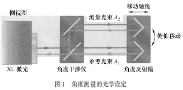
The laser beam is split into two by a beam splitter included in the angle interference mirror. A portion of the beam A1 passes directly through the interferometer and is reflected back from the angle mirror back to the laser head. The other beam A2 passes through the angular beam splitter of the angle interferometer and is passed to the other half of the angle mirror, which returns the beam through the interferometer to the laser head.
The angle measurement is obtained by comparing the optical path difference between the beams A1 and A2 (i.e., the measurement is independent of the distance between the laser and the angle interference mirror and between the angle interference mirror and the angle mirror).
2, small angle measurement
Small angle measurement is generally divided into two types, one is the measurement of small angle precision of measurement, mainly for the accuracy traceability calibration of optical angle gauge, small angle generator, self-collimator and other measuring instruments, and the angle detection range is generally not More than 1°, most of them only need to measure the accuracy within 1′, which is generally used for the angle measurement and transmission work of all levels of measurement institutes;
The other type is industrial-grade precision detection, which is mainly used to detect the yaw angle of some angular motion. The angle range may be greater than 1° or even 10°, generally as the machine pitches for CNC machine tools and coordinate measuring machines. Calibration and compensation of torsion angle accuracy.
At present, in the major metrology institutes in China, the laser small angle detection method is commonly used to realize the measurement of small angle precision. It is automatically passed by computer through the ML10 or XL80 laser interferometer produced in the UK with 150mm Invar angle optics. After measurement and correction, the angular accuracy can be better than 0.1 seconds or less.
For industrial-grade precision inspection, the laser interferometer is equipped with a 30mm ordinary angle optical mirror, and its angle range is up to ±10° with an accuracy of 0.6% or 0.2%. The performance parameters are much higher than those of the traditional four-quadrant principle. Generally, the measurement range of the four-quadrant is limited to 0.5°, and the accuracy can only barely reach 1% even after software correction.
3, 0~360° rotary axis detection
For 0~360° measurement, it must be combined with other methods on the small angle detection device. At present, the accessory device with a small angle has a circular grating, a precision multi-toothed table, and the like. Since the multi-toothed table is mechanically closed by 0~360°, the whole circumference can play the role of precision running-in of the toothed disc, and the laser interferometer with its own high precision has good precision retention. At present, the main machine tools at home and abroad This method is mostly used by inspection departments and machine tool manufacturers.
The multi-tooth table is divided into two modes: automatic and manual. Since the CNC machine tool standard must evaluate the angular positioning accuracy and repeat positioning accuracy of the machine table by 5 times of positive and negative reversal, the manual turntable will bring a lot of inconvenience. In particular, laser measurement requires that the optical path cannot be lost at will during the measurement process, and manual control of the turntable makes it more difficult to measure.
Fortunately, there is an RX10 rotary table on the market that can be used with the ML10 or XL80 laser interferometer produced in the UK. It is compatible with the standard small angle mirror mentioned above (including the optical mirror produced by Renishaw or HP in the United States). Automatic measurement of any angle and any angle step within 0~360°; when self-calibration, the angle factor and angle coefficient of the turntable can control the measurement accuracy within ±1s.
4. Analysis of laser measurement angle error
(1) Two-Angle Mirror Distance The small-angle measurement is to calculate the rotation error by measuring the change in the length of the two parallel laser paths. The laser interferometer angle measurement error is derived from the known nominal distance between a pair of mirrors in an angle mirror. The accuracy term of ±0.6% in the angle specification parameters and the plane specification parameters is based on the center-to-center tolerance between the two mirrors.
Generally, the pitch and torsion angles in the linear motion of the CNC machine tool are not large, and the accuracy index of 0.6% should be sufficient. As shown in Figure 2, the effect of the mirror rotating a small angle θ is envisaged.
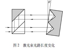
As the mirror rotates, a moving interference fringe is produced in the return beam. These stripes are detected by a photodetector located inside the laser head. The interpolation and counting circuit records the number of stripes produced by the movement.
When the mirror is stationary, the stripes remain unchanged and the photodetector detects a stable laser intensity. There is no strict linear relationship between mirror rotation and fringe count changes when performing angle measurements. When the angle is small, the relationship between the two is close to linear; but as the angle θ becomes larger, it gradually deviates from the linear relationship. The calibration software corrects this by an arc sine calculation that converts the linear stripe calculator value into a true angle reading and then calculates the angular error or displays it on a computer screen.
(2) Unconstrained tolerances When you install the indexer and assembly optics, they must be aligned as much as possible. However, it is expected that there will still be minor inconsistencies. Therefore, it is here to explain to what extent the software can reduce or even eliminate this misalignment and the effect of not collimating on the collected data:
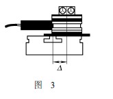
1 The rotary axes are parallel but not coincident (see Figure 3). The optics rotate during rotation; there is no measurement error; to prevent loss of signal strength, ensure  .
.
2 The rotary axes are coincident but not parallel (see Figure 4). The sinusoidal component measurement error of the acquired data is introduced. The magnitude of the error depends on δ and  In proportion to each other; to make the introduction error less than 1', ensure
  ; to make the introduction error less than 10', ensure
  .
.
DQOK toilet Bidet Spray kit is made of stainless steel or brass. It is used to clean the toilet and supply water for the toilet, so that people can have a cleaner and healthier toilet.
Toilet Bidet Sprayer Set Kit,Single Handles Toilet Set Kit,Stainless-Steel Toilet Bidet Set Kit,Bathroom Toilet Bidet Sprayer Set Kit
Heshan Dingquan Sanitary Ware Industry Co., Ltd , https://www.dqokglobal.com